Learn the step-by-step measurement sequence for assessing output factors of a variable frequency drive when troubleshooting electrical signals
Learn the 5 steps to measuring output voltage when troubleshooting VFD problems
When troubleshooting the electrical signals within a motor/drive system, think in terms of input vs. output. A variable frequency drive (VFD) transforms the input mains of constant voltage and frequency into a voltage and frequency range that can be varied to control motor torque. Troubleshooting at the input starts with testing power and supply.
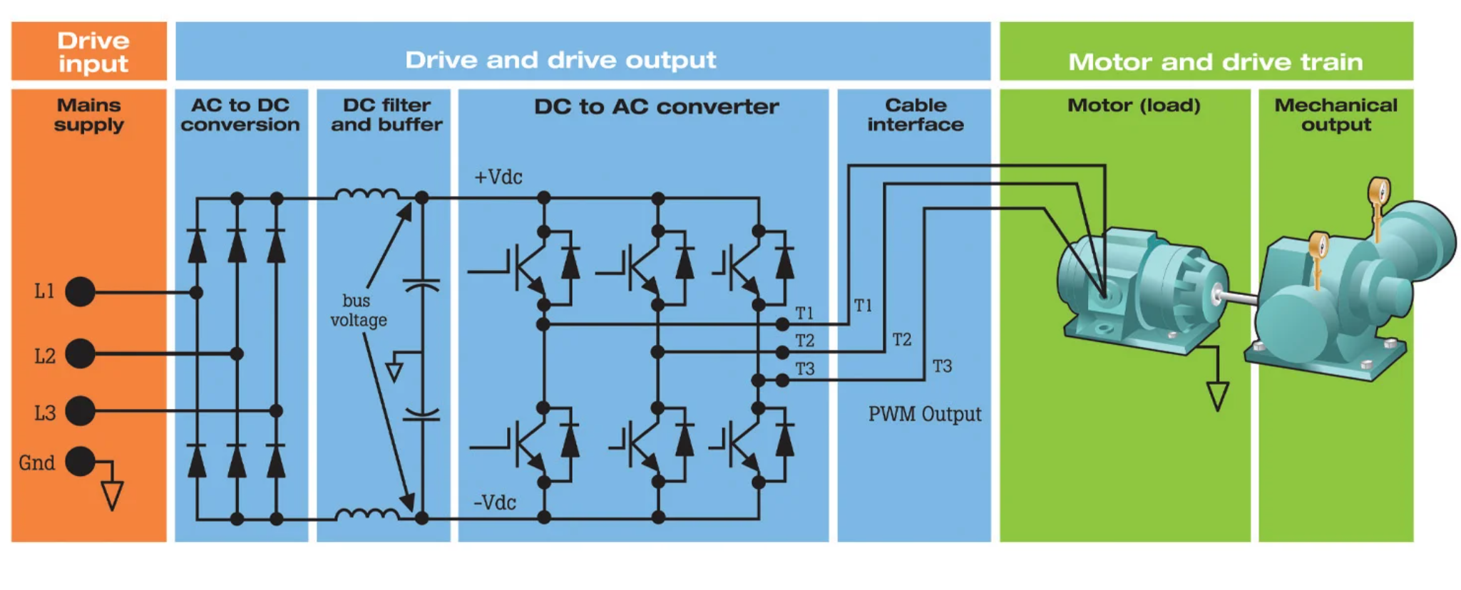
Step 1: Measure dc bus voltage
- Measure the dc bus voltage across the + and – terminals using a motor drive analyzer or digital multimeter.
- Make sure the analyzer and meter are rated appropriately to measure the voltage level.
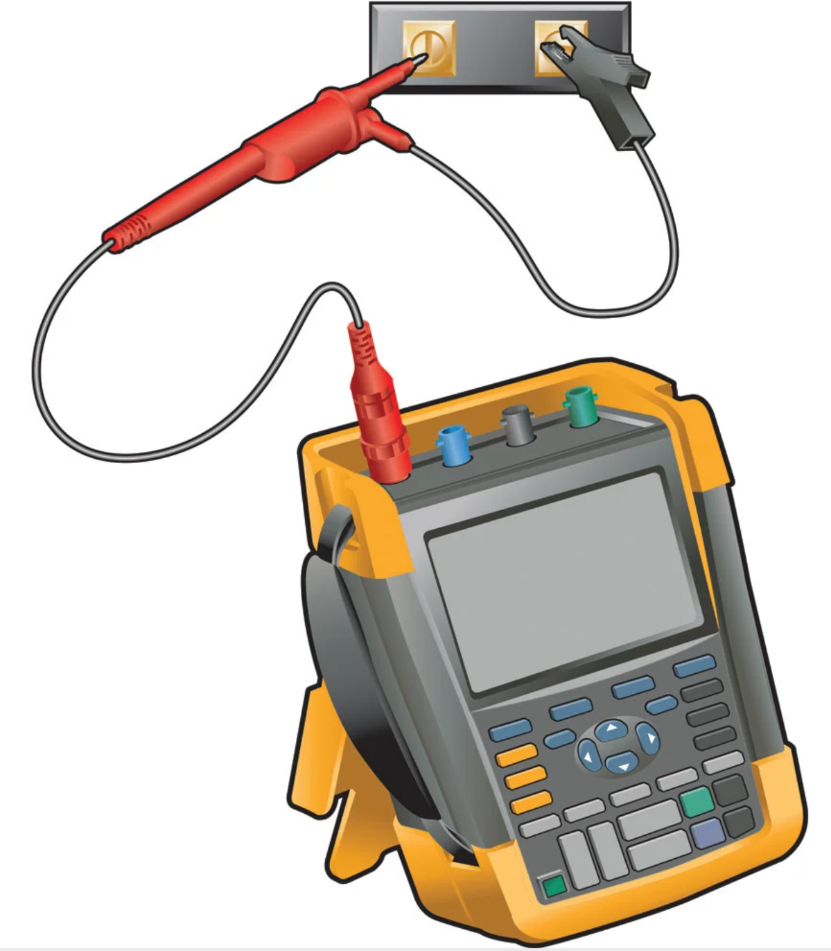
The dc bus voltage is relative to the peak voltage of the mains input. What to look for:
- dc bus voltage is ~1.414 x the rms line voltage (e.g., for a 480V ac drive, the dc bus should be ~678V dc.
- A dc voltage value that is too low can cause the drive to trip. At the cause, the mains input voltage is probably too low, or the input sine wave might be distorted by flat topping.
- If the ripple’s peaks have a different repetition level, one of the rectifier diodes is possibly malfunctioning (this is load dependent). Ripple voltages above 40V can be caused by malfunctioning capacitors or a drive rating that is too small for the connected motor and load.
Step 2: Measuring voltage and unbalance
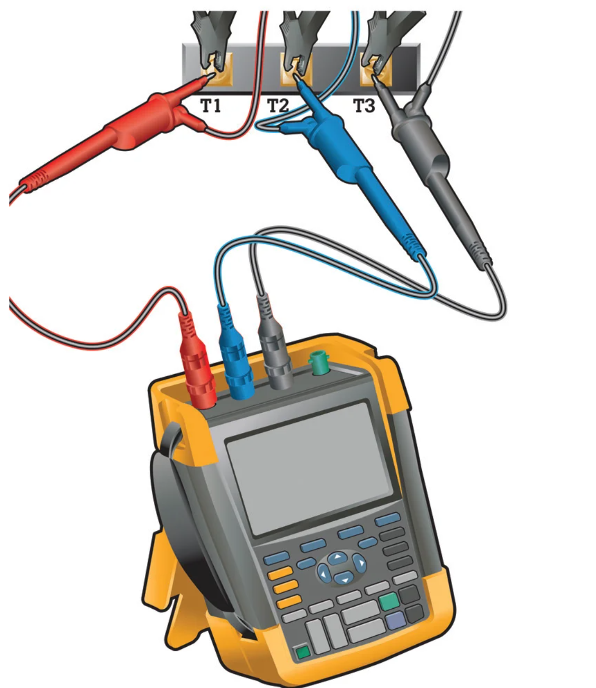
- Use a motor drive analyzer with a V PWM function connected between the three motor terminals.
- Compare the scope readings to the drive’s display values.
- Voltage drop between drive and motor terminals should not exceed 3%.
- Unbalance greater than 2% is problematic.
- Use a motor drive analyzer to check for motor voltage unbalance across the three output phases.
- Measure the voltage on each terminal and record each measured voltage for use in the next step.
- Measure voltage unbalance at full load.
Step 3: Measuring current unbalance
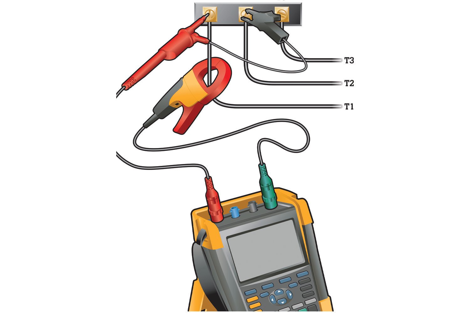
- Use a motor drive analyzer with a current clamp on all three drive output terminals separately to measure the current draw on each terminal.
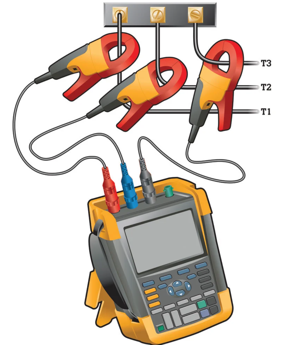
Because the current measurement will be made in a high-energy, electrically noisy environment, be sure to use the proper current clamp. If your test setup doesn’t automatically evaluate unbalance, calculate the voltage unbalance manually.
The level of unbalance should not exceed 10%.
- For every 1% of voltage unbalance, motor current unbalance will be 3 to 4%.
- If voltage unbalance is low, then excessive current unbalance could indicate shorted motor windings or phases shorted to ground.
- Generally, current unbalance for three-phase motors should not exceed 10%.
- Voltage unbalance will result in current unbalance.
- If the voltage unbalance is within acceptable limits, then any excessive current unbalance detected could indicate shorted motor windings or one of the phases shorted to ground.
Step 4: Volts/Hertz ratio
The ratio of voltage to frequency, measured in Hertz, determines the amount of torque produced by an ac induction motor.
- Use a digital multimeter with a V PWM option, where V PWM reflects the amplitude of the fundamental frequency, or a motor drive analyzer.
- Use a current clamp to measure the frequency. (It should be ~7.6 for a 460V motor, ~3.8 for a 230V motor.)
Step 5: Output reflections
Reflections occur because of an impedance mismatch or change in the current transmission path.
- Use a motor drive analyzer connected to the motor terminals
- The output reflections display a wide range of waveforms, amplitudes and durations.
- As a rule of thumb, reflections or transients >50% of nominal voltage are problematic.
Conclusion troubleshooting VFD problems
Determining the root cause of motor drive failures requires systematically performing tests and measurements at key points in the system. Specifically, regarding power supply, differentiate between power input and output and apply both different measurement techniques and evaluation criteria at each. With a little knowledge, those measurements can guide troubleshooting to the true root cause, bringing the system up as quickly as possible.